0-24v 3A Variable Power Supply using LM338
Page 1 of 1

0-24v 3A Variable Power Supply using LM338
![]() by Reza Mon Oct 08, 2018 5:18 am
by Reza Mon Oct 08, 2018 5:18 am
------------------------------------------------------------------------------------------------------------Batteries are generally used to power up the Electronic Circuit and Projects, as they are easily available and can be connected easily. But they drained off quickly and then we need new batteries, also these batteries cannot provide high current to drive a powerful motor. So to solve these problems, today we are designing our own Variable Power Supply which will provide Regulated DC voltage ranging from 0 to 24v with a maximum current up to 3 Amps.
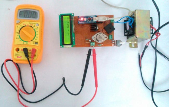
For most of our Sensors and Motors we use voltage levels like 3.3V, 5V or 12V. But while the sensors requires current in milliamps, motors like servo motors or PMDC motors, which run on 12V or more, require a high current. So we are building here the Regulated Power Supply of 3A current with the Variable voltage between 0 to 24v. However in practical we got up to 22.2v of output.
- Here the voltage level is controlled with help of a Potentiometer and voltage value is displayed on Liquid Crystal Display (LCD) which will be driven by an Arduino Nano. Also check out our previous Power supply circuits:
-Materials Required:
Transformer - 24V 3A
Dot board
LM338K High Current Voltage Regulator
Diode Bridge 10A
Arduino Nano
LCD 16*2
Resistor 1k and 220 ohms
Capacitor 0.1uF and 0.001uF
7812 Voltage Regulator
5K variable Pot (Radio Pot)
Berg stick (Female)
Terminal Block
-How it works:
A Regulated Power Supply (RPS) is one which converts your AC mains into DC and regulates it to our required voltage level. Our RPS uses a 24V 3A step down transformer which is rectified into DC using a diode bridge. This DC voltage is regulated to our required level by using LM338K and controlled by using a Potentiometer. The Arduino and LCD are powered by a low current rating Voltage regulator IC like 7812. I will explain the circuit step by step as we go through our project.

Reza- Admin
- Posts : 8
Join date : 2018-10-07
Age : 44
Location : Iran -

Page 1 of 1
Permissions in this forum:
You cannot reply to topics in this forum